Hydraulic Directional Control Valve Symbols Pdf
Reading Fluids Circuit Diagrams Hydraulic Pneumatic Symbols
Book 2 Chapter 8 Directional Control Valves Hydraulics Pneumatics
China Electrical Operated Directional Control Valve Hydraulic Control Valve Hoyea

Directional Control Valves Symbols Hydraulic Valve
Pneumatic Circuit Symbols Explained Library Automationdirect
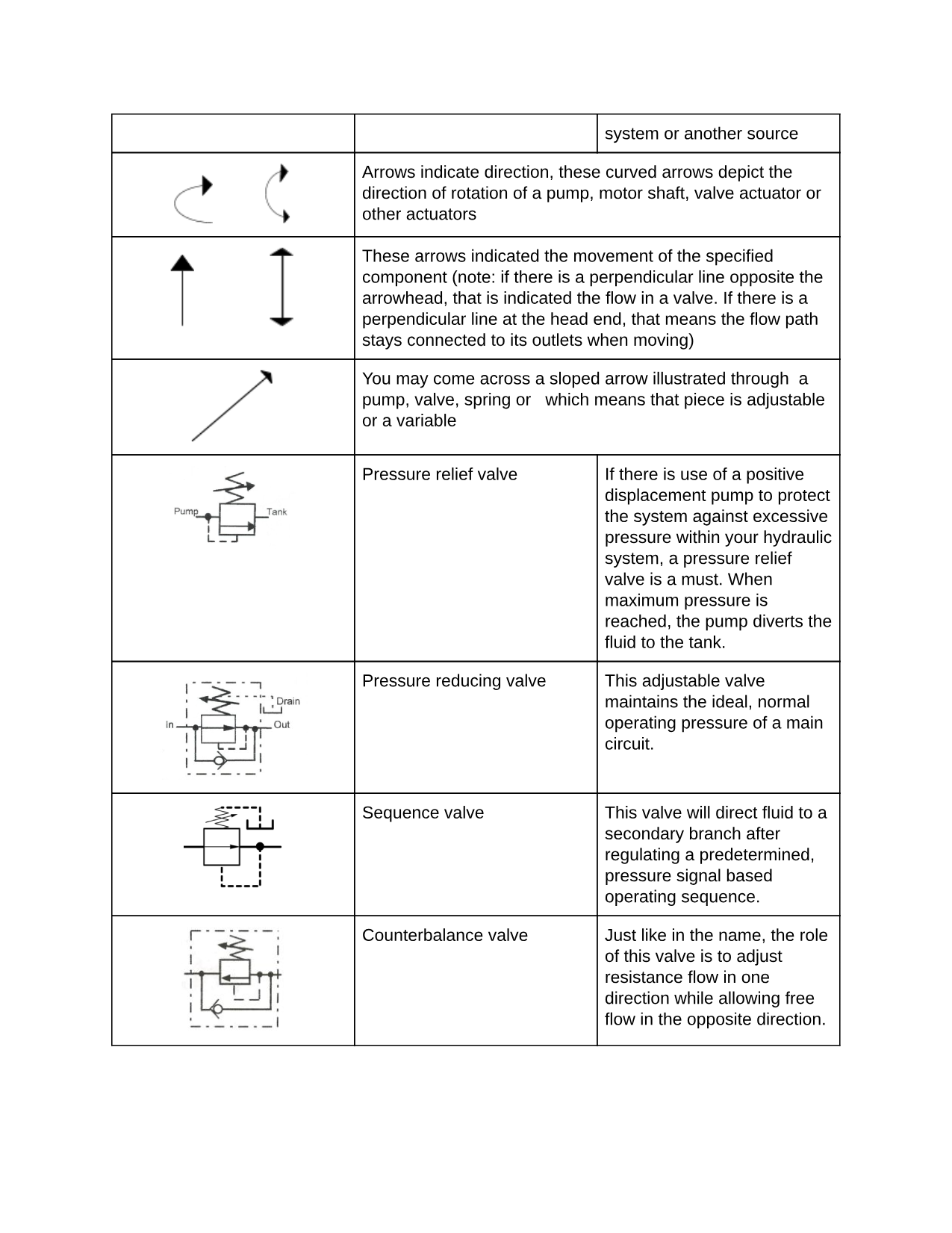
Hydraulic Symbols Introduction

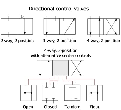
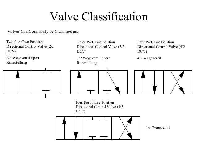
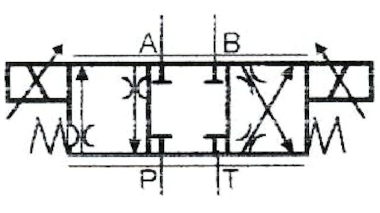
Each position the valve can take is represented by a square.
Hydraulic directional control valve symbols pdf.

Hydraulic Symbology 201 Industrial Directional Valves
Hydraulic And Pneumatic P Id Diagrams And Schematics Instrumentation Tools

Figure C 2 Hydraulic Schematic Sheet 6 Of 7

Engineering Essentials Directional Control Valves Hydraulics Pneumatics

Valve Symbols Tameson

Chapter 12 Infinitely Variable Directional Valves Hydraulics Pneumatics

Hydraulic Power Pack This Ebook Answer You All Questions About Hydraulic Power Unit
Chapter 10 Directional Control Valves Part 3 Hydraulics Pneumatics

The Secret Of Hydraulic Schematics Btphydraulics Pdf Free Download
Hydraulic Symbols Winnellie Hydraulics

Directional Valve Symbol Hydraulic Systems Valve Hydraulic Fluid

China Hydraulic Directional Spool Valve Wh10 16 25 32 Manufacturers Suppliers And Factory Wholesale Products Ningbo Zhenhai Finotek Machinery Co Ltd

Chapter 4 Iso Symbols Hydraulic Systems Symbols Piping And Instrumentation Diagram

Pneumatic Circuit Symbols Explained Symbols Electronic Schematics Valve
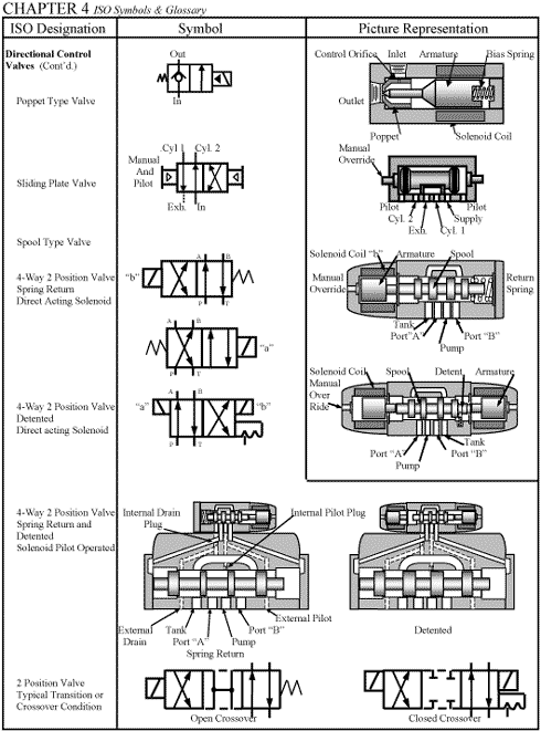
Chapter 4 Iso Symbols Hydraulics Pneumatics
Understand Valve Versatility For Better Designs Hydraulics Pneumatics
How To Read A Schematic Understanding Of Graphical Symbols Used In Fluid Power Drawings Air Hydraulic Equipment Inc

Component Circuit Symbols Pneumatic Components And Wp032e65 Electronic According To Wikipedia Names 3 Electronics Ppt Of A 1 H Circuit Diagram Circuit Symbols
Https Encrypted Tbn0 Gstatic Com Images Q Tbn 3aand9gcqtun4kzwdkqxe4loxy5d7 M8df Sqvlrurmamridk Ltubrbnd Usqp Cau

Hydraulic System For Beginners Fundamentals And Applications Of Mechanical Engineering Engenharia Mecanica Comandos Eletricos Automacao Industrial

Types Of Directional Control Valve Dcv Based On The Fluid Path Control Valves Industrial Automation Plc Programming Scada Pid Control System
Book 2 Chapter 14 Proportional Control Valves Hydraulics Pneumatics

Chapter 4 Iso Symbols Other Technologies Content From Hydraulics Pneumatics Symbols Hydraulic Systems Electrical Diagram

Chapter 4 Iso Symbols And Glossary Part 2 Hydraulics Pneumatics In 2020 Hydraulic Systems Glossary Electrical Diagram
Source : pinterest.com
